| Tills Palm Pages | http://www.harbaum.org/till/palm |

| Convert your cradle into a battery charger |


For german readers:
Zu dieser Bauanleitung ist in c't 7'99 ein Artikel erschienen, der
auch im
Netz abgerufen werden kann.
 Figure 1: Charging ... |
This page describes a circuit that can be integrated into a Palm Pilots cradle and allows automatic charging of the batteries of a Palm inserted into the cradle. The charger was successfully tested with all Palms except the Palm V (which has it's own charging cradle) and the Palm VII (this should work, i just don't have a Palm VII to give it a try). The charging electronic allows fast charging of NiMH batteries. It works with the Palm on or off and, therefore, allows simultaneous charging and HotSync. Even with defective or removed batteries, this charging unit regulates its output voltage to a level that will not affect the Palms internal electronics. The charging unit fast charges the batteries until they are full and then starts tickle charging the batteries to prevent discharging. A modified charging cradle can be used with a unmodified Palm (although it will not charge him) and a modified Palm can be securely used with a unmodified cradle without any limitations. |
| Modification of the Palm |
|
To allow charging via the cradle a little modification needs to be applied to the Palm Pilot. You need to insert a diode (D5) between the unused pad 9 of the Palms HotSync connector and the positive battery terminal to allow charging of the batteries, but to prevent damage to the batteries/Palm due to possible shortcuts at the HotSync connector during transport. The diode has to be attached to pad 9 of the HotSync connector. This pad is unused and even unconnected in a Pilot Pro or Personal and you have to solder a thin wire carefully to border of the pad to ensure that no solder gets onto the center of the gold contact. In the Palm III, Palm IIIx and Palm IIIe there is a thin track connected to the unused pad going to a spare solder pad on the backside of the PCB. This pad should not be used for soldering, since it is placed beneath the contact rubber of the four function keys. Instead you should remove some of the green isolation on the track attached to pad 9 and solder the wire there. Be careful not to remove the isolation from the tracks beside or not to shorten tracks. Once you have connected pad 9 with the diode and the diode to the positive battery terminal you are finished inside the pilot. We continue with ... | 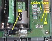 Figure 2: Palm Modification |
| Modifying the Cradle |
The charging circuit itself is built into/behind the cradle. Therefore, you have to open the cradle first. To open the Palm III/x/e cradle you just unscrew the bottom and everything falls apart. Opening the older cradle is a little more difficult and you have to slide the small front with the HotSync button down. Perhaps you need to squeeze the two plastic nibbles at the bottom to be able to remove the front. The cradle of the Palm III offers enough unused space to insert the charger into (see figure 3). At one of the old cradles you have to attach the charging unit somewhere at the backside of the cradle.
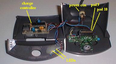
Figure 3: Cradle Modification
| The Charging Circuit |
The charging circuit is based on the MAX712CPE from Maxim. The whole circuit is 4.2 cm * 2.7 cm (1.7 inch * 1 inch) in size and fits inside the Palm III cradle. Please don't use the small GIF picture on this page to etch the PCB use the EPS file or the 600 dpi GIF image instead. The layout is mirrored. If you print this directly onto a foil you need to place it with the printed side to the PCB for the photo transfer. Note that the holes for the diodes and the transistor need to be 1mm in diameter, all other holes are drilled with 0.8mm.
|
The MAX712 contains a constant current source with voltage limiter and timeout counter. The MAX712 is programmed via four configuration pins (PGM0 to PGM3). In this circuit the MAX712 is configured to charge two NiMH cells (PGM0 tied to V+ and PGM1 left open). The two cells are inserted into the Palm and connected via pad 9 of the HotSync connector to one terminal of the diode D1. The charge current is switched by transistor T1, which is controlled by the charge controller U1. The controller continuously monitors the voltage over resistor Rsense. A value of 2 ohms limits the charge current to exactly 125mA. The charge current can be modified by choosing another value for Rsense (see the data sheet for further details). The value of 125mA was chosen for cells with a capacity of 450-550mAh and allows to charge these batteries within four hours. With PGM2 and PGM3 the controller is instructed to terminate the charge after at most 4.4 hours, even if no full condition was detected. This timeout ensures secure operation even with defective batteries and prevents over-charging. |
 Figure 4: Schematic of charger |
The controller monitors constantly the battery voltage via pin BATT+. During charge this voltage increases constantly until it remains constant at the end of the charge. The controller now switches to tickle charge to ensure that the batteries stay full. Another pin compatible charge controller (MAX713) is available which allows charging of NiCd batteries. Although NiCd batteries are cheaper than NiMH ones they have only half the capacity of NiMHs and they have the famous memory effect which causes NiCd batteries to loose capacity if not emptied completely before recharge. I strongly recommend NiMH batteries, they are cheap, they are easy to buy and they have half the capacity of good alkalines.
 Figure 5: PCB for charger (EPS-File) |
 Figure 6: Charger components (EPS-File) |
Most hi-quality chargers allow to auto detect the number of cells connected. This feature would be fatal for the Palm Pilot, since such chargers increase the charge voltage to determine the number of cells. This increased voltage may damage the Palms electronics. The MAX712 does not have such a feature. Instead he can be programmed to support a specific number of cells (2 in this circuit). This ensures that the MAX712 limits the maximum output the voltage to twice its reference voltage (which is 2 volts in this circuit) limiting the overall output voltage to 4 volts. The diode D5 built into the Palm drops 0.7 volts giving a maximum voltage of 3.3 volt applied to the Palms internal electronics. This value is secure and will only be reached if the batteries are defective or removed or no Palm is inserted at all. During normal operation the voltage will reach at most 2.8 to 2.9 volts. If the voltage reaches the 4 volt bound (3.3 in the pilot) the charger stops charging and waits for the Palm to be reinserted. Once it is reinserted, the controller restarts fast charge operation, until the batteries are full. This way the charger can be always be powered on. It will restart charging every time, the Palm is reinserted.
The charging unit may be glued to the backside of the front of the Palm III cradle (see figure 3). Be careful to place the PCB close to the bottom of the cradle. You'll have problems closing the cradle otherwise. The power connector may be placed at the back of the cradle. Please verify, that the PCB and the connector do not touch when the cradle is closed (see figure 3).
Two LEDs indicate the state of the charge process. The green LED is always on if the charger is powered on. The yellow LED indicates fast charging in process and is off if no Palm is inserted or if the batteries are full and the charger switched to tickle charge. The LEDs should be placed somewhere at the front of the cradle (see figures 1 and 3).
The MAX712/713 has the additional capability of monitoring the temperature of the batteries. This feature is not used in this circuit since it would require additional connections to the Palm and additional parts inside the Palm. Because of the low charge current of 125 mA the batteries are not in danger of overheating, anyway.
| The power supply |
The power supply should be as cheap as possible. It must be capable of driving a current of 200mA at a voltage of approx. 7.5 volts DC. The power supply must not be grounded. A grounded power supply would interfere with the grounding of the PC connected to the RS232 connector of the cradle and cause the charge current regulator to malfunction. Most cheap wall cubes won`t be grounded so choose a very cheap one.
| Energy Mr. Scott |
After the soldering is completed and all connections are carefully verified (are all diodes/capacitors the right direction?) you may perform the first tests. First connect the power to the circuit without inserting the MAX712. D2 prevents the circuit from damage due to wrong polarity of the power source. The power LED (D4) should be on, the charging LED (D3) off. The circuit should draw a current of about 15mA.
Now remove the power supply and insert the MAX712. With power applied the charging LED should still be off. You should now measure the voltage between pad 10 (GND) and 9 of the cradle (looking from the front onto the cradle pad 10 is the rightmost connector at the cradle). This should show quite exactly 4 volts. You might now insert the NiMH batteries into your Palm and place it into the cradle. The charge LED should light and the input current of the hole thing should be about 150mA. Congratulations, you`ll never have to buy batteries again for your Palm! For correct battery handling you should install a program like my battery hack or something similar and switch the battery panel to NiCd/NiMH display.
| Caveats |
There may be some minor problems with this circuit. First the circuit is not connected to the batteries exactly the way Maxim suggests in the data sheet. Due to the fact that the connection between the Palms electronic and the batteries is different from the MAX712 application, the charge controller cannot monitor the batteries separately. Instead it's monitoring the batteries and the internal pilot electronics causing inaccurate values for the charge current. This may cause the charge controller to terminate the charge process too early. A similar effect can be caused due to a weak power supply. Anyway, this problem does not affect normal operation. If the batteries are not completely recharged during a charge process just reseat the Palm into the cradle causing the charge controller to restart charging.
Another thing you need to be aware of is never use alkaline batteries or refresh-able alkalines with the charger. You may use alkalines as long as you don't apply power to the charge unit in the cradle, but never try to charge alkalines. This may damage the charger and your Palm. It is recommended to use NiMH batteries with a MAX712 based charger and NiCd batteries with a MAX713 based unit only.
| Components |
|
|
|
| References |
| Files |
| Tills Palm Pages | Get in touch! |