| Tills Palm Pages | http://www.harbaum.org/till/palm |

| A Tilt Sensor Interface for the Palm Computing Platform |
|
Adding sensorics to the PalmPilot is an interesting issue. This little application will show you how to get your PalmPilot to measure acceleration and gravity. The sensor used in this application is the ADXL202AQC from analog devices.
There are currently two sensor interfaces:- An external dongle working with all palm devices (incl. Palm IIIc and the TRG Pro)
- and an internal solution for the Palm III and Palm Professional
| The Tilt Dongle |
 Figure 1: The Tilt dongle |
The new tilt dongle plugs into the HotSync port of any device of the Palm V series, the Palm III series (incl. IIIc) the TRG-Pro or any Pilot with at least PalmOS 2.0. With the new dongle driver library all tilt enabled programs like mulg can take advantage of the new sensor interface. The dongle does not require any modifications to the palm device. |
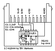 Figure 2: Dongle internals |
I've built the dongles into the cases of HotSync connectors. You can either cut one off a HotSync cable (quite expensive, but that's what i did) or buy one from 3com's suppliers, but you'll need to be registered at 3com to get access to those addresses. The cases are glued and you'll have to pry them open with a screwdriver or something like that (i used to poke the screwdriver into the hole for the cable to avoid scratches in the case).
The chip itself can be ordered at analog devices' web page and can be glued with the pins bent up into the connector case. All connections are then done on top of the chip with some thin wires. Finally (and after a functional test) use some glue to close the connector case and you are done.
With this new tilt dongle, the tilt chip is controlled and powered via the rs232 drivers of the palms HotSync interface. This means that the drivers are enabled during tilt operation and hence, drain the batteries like the do e.g. during HotSync operation.
Furthermore the IrDA interface shares some internal hardware with the HotSync port and can't be operated concurrently with the tilt dongle. An attached but unused tilt dongle will not affect IrDA operation, but the tilt sensor and IrDA interface cannot be enabled at once.
| Internal tilt sensor for Palm III and Palm Professional |
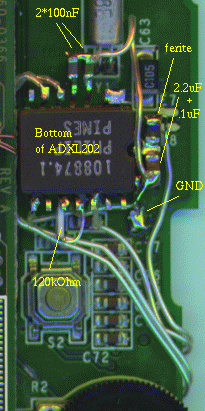
For the internal version, the sensor is attached to four (apparently) unused pins of the DragonBall CPU.
These four pins are:- Pin PJ7 (72) is used to power the sensor. Since the sensor draws about 0.4mA at 3 volts this does not harm the IO pin.
- Pin PJ6 (73) is used to switch the ADXL202AQC into test mode and back.
- Pin PE6 (82) is used to read the ADXLs X duty cycle output.
- Pin PE5 (83) is used to read the ADXLs Y duty cycle output.
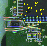 Figure 4: Connecting the ADXL202AQC to the CPU |
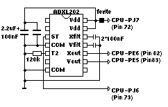 Figure 5: Schematic |
| Installation in the PalmPro and Personal (by Howard Samuels) |
|
The Pilot Pro has no test points on the PC Board, so you do have to solder
directly to the processor pins. First, use a super-fine tip soldering iron.
Second, solder under a microscope. If you follow these two suggestions, the
biggest problem will be counting the pins to solder to the correct ones. The correct corner for the pins of interest is the lower right, if you orient the board with the batteries at the bottom. Be careful not to melt the plastic case of the battery compartment. Vdd goes to the right most pin on the bottom row, ST goes to the bottom pin of the right row, and the two outputs go about 10 pins up the right side.
| 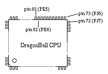 Figure 6: Attachment to the PalmPro |
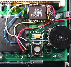 Figure 7: Sensor installed in Howards PalmPro |
Till's website includes the pin numbers that you have to solder to and
has the pin names (something like PJ6 and PJ7). You can find the
numbers from the Dragonball processor data sheet, which he points to as well. Note that you can't just scratch the solder mask to get to the ground plane. There are a couple of places where you can solder a wire to ground. The right side of C10 is one convenient location for ground. Take the yellow tape that holds the beeper wires, and use it to insulate the daughter board connector. The xl202 goes to the upper right of the processor, just below the connector. I put mine in dead bug position, with the notched end pointing to the right. This ends up being the same orientation as the Palm III installation.
|
| Hardware test |
To test the sensor you might use the test application (source) or you can use mulg. The chip is switched on and off via pin PJ7. The library does this automatically whenever it is in use by an application and whenever the Palm goes into sleep (power down) mode or comes awake again (power up). While the sensor is in use, it draws about 0.4mA which is about 4 percent of the palms nominal usage.
| The tilt library for the internal sensor (V1.1 12/13/1999) |
All tilt enabled programs (accel_test V1.2, StepCounter V1.1 and Mulg IIe) use a generic tilt sensor driver. The driver for the internal hardware presented on this page is included with all tilt enabled programs. Future tilt hardware may come with its own driver and will allow the tilt enabled applications to access future sensors via this unified interface.
For a demo application see the source of the accelerometer test application which includes sources and an api description for the demo application and the driver.
Driver history:
V1.0: Initial version
V1.1: Prior version didn't power down the sensor on termination of client.
| The tilt library for the external tilt dongle (V1.5) |
The tilt dongle driver replaces the internal driver when you are using the dongle instead of the built-in sensor. The dongle driver works with all current genuine palm models (the whole III and V families incl. the IIIc and the M50x).
Since the dongle attaches to the serial interface of the palm, the serial interface must not be in use by another application while using the dongle.
Since version 1.4 IR receive doesn't need to be disabled for tilt dongle operation.
Driver history:
V1.0: Initial version for the Palm V only
V1.1: Version for all genuine palm machines except the VII and IIIc
V1.2: Fixed some problems with my Palm IIIx
V1.3: Fixed IrDA problems
V1.4: New hardware interfacing compatible with Palm IIIc and the IR interface of most devices; no need to disable IR during dongle operation
V1.5: Added support for Palm M5xx (and perhaps M130 etc.)
| The tilt hack for the internal sensor (V1.5 10/13/2002) |
This little hack is released under the GPL and maps the tilt sensor input onto the hard keys. This way you can play most games with the sensor or just scroll text by tilting the pilot. Please read the manual carefully before using this hack.
This hack does not work with the tilt dongle, since it would interfere with any other application using the HotSync port.
Hack history:
V1.0: Initial version
V1.1: More precise sensivity adjustment
V1.2: Simple sensor power management (causes phantom events on power up and down, but saves power)
V1.3: New option to report state changes only once.
V1.4: Another new option to report only the axis that is more tilted. Added help page.
| Third party tilt apps |
Currently there's only few software beside my programs that makes use of the tilt interface:
- Orit Kruglanskis tilt enabled poems
- Karl-Petter Åkessons MIDI shaker
| Driver downloads |
Tilt dongle: Internal sensor:
- The tilt sensor driver V1.1 is included e.g. in the archive of the accelerometer test application
- Tilt hack V1.4 with source
- Accelerometer test application V1.4 with graphic output and driver library V1.1
- Accelerometer test application V1.4 and driver library V1.1 source for gcc/pilrc
- Accelerometer test application V1.0 source for Code Warrior (contributed by Gavin Maxwell)
- Step counter
- Mulg II
| References |
| Tills Palm Pages | Get in touch! |


