

News: Now with lcd4linux driver
I recently purchased 10 SLM1608 (SLM1606) LED matrix display units from Ebay (you might also contact the seller directly at op16@gmx.de). These are 16x16 LED matrix units with a green and a red LED per pixel allowing each pixel to be switched to either green, red, amber or off. The goal of this LEDMATRIX project was to build a 80x32 pixel display by arranging the displays in two rows with 5 displays each giving a total of 16*16*2*2*5 = 5120 LEDs to be controlled individually.
Fortunately these displays come with interated controllers and the data can be shifted into a single display using as few as 6 digital signals. By multiplexing some of the select signals all 10 displays can be controlled with a total of ten wires. Using a cheap ATmega32 microcontroller all ten displays can easily be controlled and updated in real time.
This kind of display is usually controlled via RS232. This has the disadvantage of being very slow and the display data is limited to simple text messages only with the microcontroller of the display doing the actual text drawing. Instead of doing it the same way i decided to use an ethernet interface for the LEDMATRIX display. Even the most simple ethernet interface i am using is fast enough to transfer graphics data in realtime from a PC to the display allowing to update the entire screen 50 times a second. The ethernet support of LEDMATRIX is based on the cirrus logic cs8900 chip which is e.g. supported by the free Procyon AVRlib which has been used for this project.
The LEDMATRIX additionally includes a simple speaker allowing to e.g. notify the user of a new message being displayed. Furthermore a TSOP1736 IR receiver can optionally be connected. This device receives and decodes the IR signals used by ordinary TV remote controls. By returning informtion about received IR signals to the controlling PC, the displays contents may e.g. be remotely changed using a simple spare IR remote control.
This whole project is open under the GPL. This means that you get full access to the firmware source code as well as to the schematics and the PC companion software.
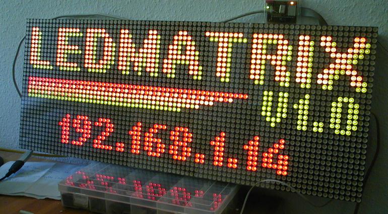
After startup the display shows the LEDMATRIX splash screen with the firmware version number and the current IP address.
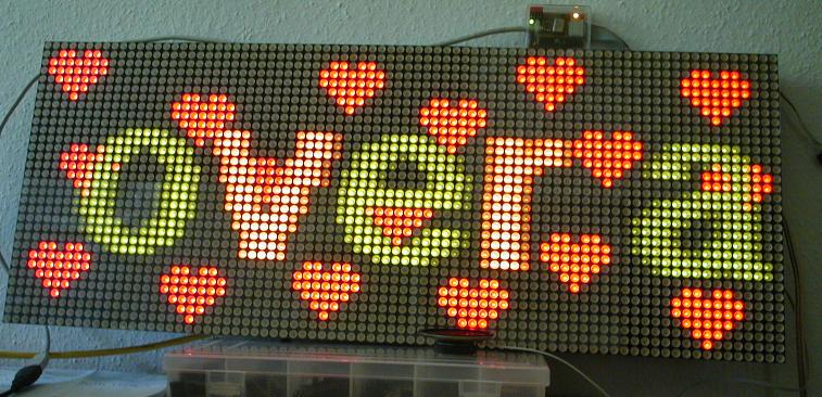
Once the PC is accessing the display any data can be displayed like e.g. a long transparent scroll text with some static small red hearts in the background.
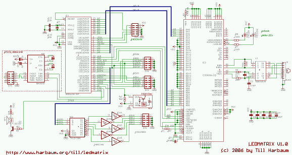
The entire device could easily be built with standard wired components ... if there wasn't the cs8900 ethernet controller which is available in SMD technology only. Fortunately, some companies sell this chip ready to use on a simple pcb like e.g. this one (search for a device called easyToWeb-CS8900-16bit). This isn't the cheapest solution but it allows the entire device to be built manually.
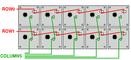
I mounted the ten displays in two rows with five displays each. The five displays of one row share the main control signals (red, green, bright, clock and reset) while the five columns share the select signal. Both rows have seperate red and green signals. This way i can update both displays in a column at once and one column after the other. See the image below for the wiring on the real thing.

The image below shows the wiring diagram. See the schematic for details on the three connectors (row0, row1 and column). Three signals (bright, reset and clock) are present on both the row0 and row1 connectors and are distributed to all 10 displays at once. The red and green pixel data are driven by seperate signals (red0/red1 and green0/green1) on row0 and row1.
The five columns are connected to the columns connector. Only one column can be selected for update at a time.
Once of the 16x16 displays draws about 2 A if all LEDs are switched to amber. My application does not reach the limit of 3.2 A specified for the displays, since during the display update times the displays are switched off. The resulting image still is very bright and clear.
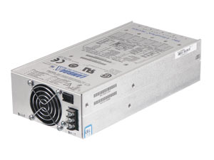
With one display drawing 2A @ 5V, the power supply of the LEDMATRIX needs to source all ten displays and thus needs to be able to provide a total current of 20A. You might be able to find a cheap old PC power supply that delivers 20A on the 5V line. I am using a Lambda UAZ1G 30A power supply. I made some small modifications to the device. I e.g. replaced the noisy small fan with a very quiet 70mm one. There's much unused space in this power supply so the fan can easily be replaced with a bigger one and e.g. adding a power switch and a connector for a standard power supply cable isn't a problem. Even with the fan completely switched off and with the display at full amber brightness (all 5120 LEDs switched on) the power supply barely gets warm ...
The LEDMATRIX software consists of two parts: the firmware and a network client application for the PC. The firmware provides the basic hardware functionality while the pc application calculates the actual images to be displayed. Even the most complex animations can be done this way since all image processing is taking place on the PC. The entire display can be updated 50 times a second from the PC allowing e.g. for smooth scrolling.
The PC client application is available for linux and for windows. Binaries for both operating systems are included in the archive below.
If you use Linux you can use the LEDMATRIX to display system information and the like just by using the LEDMATRIX driver for lcd4linux.
| Home | Till Harbaum <Till@Harbaum.org> |